
Em nosso último tutorial demonstramos como efetuar o controle de um servo motor sem a utilização da clássica biblioteca servo.h. No projeto, utilizamos as funções de delay disponíveis na IDE do Arduino. Também mencionamos que era a forma mais simples mas não a melhor forma de se controlar um servo. Hoje você aprenderá a controlar um servo motor 9G por interrupção, que será muito mais eficiente.
As interrupções tornam possível o uso de um processador para execução de diversas tarefas. Em seu computador, toda vez que movimenta o mouse, utiliza um periférico USB, dá entradas no teclado, você está gerando interrupções por exemplo. Caso o processamento das tarefas fosse realizado por polling (laços de programa que prendem o processador a uma única tarefa), a execução de várias tarefas seria inviável. Vale salientar que nenhum processador é capaz de executar duas tarefas ao mesmo tempo. Nos microcontroladores isto não é diferente, pois os mesmos também são processadores.
Conectando o Servo Motor ao Arduino
O hardware do projeto de hoje é bem simples. Conecte um servo motor na pino digital 4 do Arduino e um potenciômetro linear de 50k no pino analógico 0 (Figura 2). Um detalhe importante é que o presente projeto funcionará apenas para Arduinos que utilizem o microcontrolador Atmega328P, tais como o NANO, UNO e DUEMILANOVE. O Arduino Mega não funcionará nesta aplicação, pois utiliza o MCU Atmega2560.
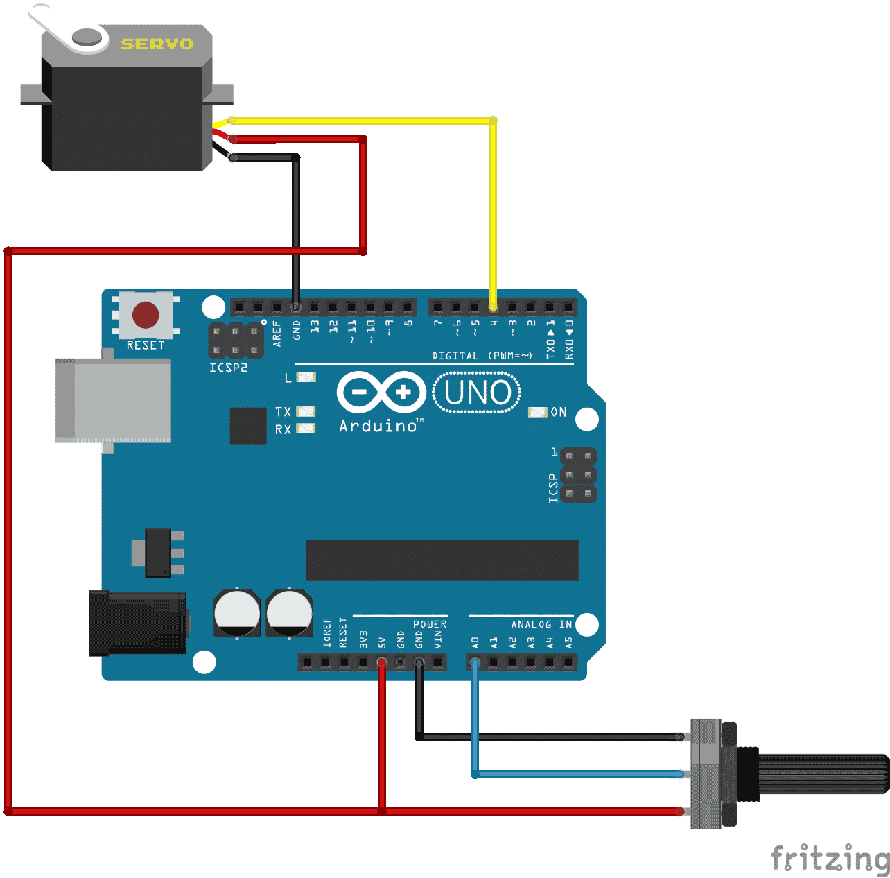
Figura 2 – Hardware do projeto
No software, configuramos os registradores do Atmega328P para trabalharem com o Timer2. O Timer2 consiste em um registrador utilizado para contagem e temporização. Através dos registradores especiais TCCR2A, TCCR2B, TCNT2 e TIMSK2 configuramos a operação do timer no modo normal, com prescaler 1:1024, inicializando o conteúdo do Timer2 em zero e habilitando a interrupção do Timer2, respectivamente.
Em suma, o Timer2 vai contar cada ciclo de máquina do processador até chegar ao valor limite (255 decimal). Quando houver a transição de 255 para 0 (reinício da contagem), ocorre o estouro (overflow) do Timer. Esse estouro vai gerar uma interrupção no processador, desviando o código para a função ISR(TIMER2_OVF_vect). O algoritmo presente nesta função de interrupção é destinado à criação do PWM, referente ao diagrama de tempos dos servo motores.
Programa controle de servo motor por interrupção
O código completo está explícito no Box 1 e totalmente comentado.
/*
   Aula 68 - Controle de Servo Motor por Interrupção (Timer Overflow)

   Autor: Eng. Wagner Rambo
*/


// --- Mapeamento de Hardware ---
#define servo1  4     // Servo 1 conectado no pino digital 4
#define pot    A0     // Potenciômetro de controle no pino A0


// --- Variáveis Globais ---
unsigned char duty = 0x00;    //Variável para alterar o duty cycle
int adc = 0x00;               //Armazena leitura analógica


// --- Rotina de Interrupção ---
ISR(TIMER2_OVF_vect)
{

    if(digitalRead(servo1))               //Saída servo1 em high?
    {                                     //Sim...
         TCNT2 = duty;                    //Timer2 recebe valor atual do duty
         digitalWrite(servo1, LOW);       //Saída do servo1 em low
    } //end if servo1
    else                                  //Senão...
    {
          TCNT2 = 255 - duty;             //Timer2 recebe valor máximo menos valor do duty
          digitalWrite(servo1, HIGH);     //Saída do servo1 em high

    } //end else

} //end interrupt


// --- Configurações Iniciais ---
void setup()
{
     pinMode(servo1,OUTPUT); //saída para o servo1
     pinMode(pot, INPUT);    //entrada para o potenciômetro

     TCCR2A = 0x00;   //Timer operando em modo normal
     TCCR2B = 0x07;   //Prescaler 1:1024
     TCNT2  = 0;      //Conteúdo do Timer2 inicia em zero
     TIMSK2 = 0x01;   //Habilita interrupção do Timer2

     digitalWrite(servo1, LOW);

     duty = 16;       //Inicia duty no valor mínimo para o servo

} //end setup


// --- Loop Infinito ---
void loop()
{
   //Aguarda Interrupção...

   adc = (analogRead(pot))/64;  //adc recebe a leitura ad do potenciômetro

   duty = adc + 16;             //valor do duty atual mais shift de 16 (cálculos explícitos abaixo)


} //end loop


/*
    Ciclo de máquina = 1/Fosc = 1/16E6 = 62,5ns = 62,5E-9s

    Estouro = (256 - TCNT2) x prescaler x ciclo de máquina
            = (256 -     0) x   1024    x    62,5E-9
            = 16.384ms


    Regra de 3

    256     n

    16ms    1ms

*/
Para download completo dos arquivos sobre este post de controle de servo motor por interrupção, utilize este link.
Gostou? Deixe seu comentário logo abaixo.
Olá!!
estou com um projeto em que o motor deve ficar ligado o dia todo de acordo com um sensor de batimentos cardíacos. Porém o motor vem queimando. Penso que se eu desligar ele no código, para ele funcionar somente quando o sensor detectar, exigiria menos dele. Porque parece que ele fica trabalhando mesmo quando nao detecta nada. Desligar ajudaria? como fazer isso?
segue o código:
#include
/*
Every Sketch that uses the PulseSensor Playground must
define USE_ARDUINO_INTERRUPTS before including PulseSensorPlayground.h.
Here, #define USE_ARDUINO_INTERRUPTS true tells the library to use
interrupts to automatically read and process PulseSensor data.
See ProcessEverySample.ino for an example of not using interrupts.
*/
#define USE_ARDUINO_INTERRUPTS true
#include
/*
The format of our output.
Set this to PROCESSING_VISUALIZER if you’re going to run
the Processing Visualizer Sketch.
See https://github.com/WorldFamousElectronics/PulseSensor_Amped_Processing_Visualizer
Set this to SERIAL_PLOTTER if you’re going to run
the Arduino IDE’s Serial Plotter.
*/
const int OUTPUT_TYPE = SERIAL_PLOTTER;
/*
Pinout:
PULSE_INPUT = Analog Input. Connected to the pulse sensor
purple (signal) wire.
PULSE_BLINK = digital Output. Connected to an LED (and 220 ohm resistor)
that will flash on each detected pulse.
PULSE_FADE = digital Output. PWM pin onnected to an LED (and resistor)
that will smoothly fade with each pulse.
NOTE: PULSE_FADE must be a pin that supports PWM. Do not use
pin 9 or 10, because those pins’ PWM interferes with the sample timer.
*/
const int PULSE_INPUT = A0;
const int PULSE_BLINK = 13; // Pin 13 is the on-board LED
const int PULSE_FADE = 5;
const int THRESHOLD = 550; // Adjust this number to avoid noise when idle
/*
All the PulseSensor Playground functions.
*/
PulseSensorPlayground pulseSensor;
/*
Make a heart servo, the pin to control it with, and a servo position variable
*/
Servo heart;
const int SERVO_PIN = 6;
int pos = 90;
void setup() {
/*
Use 115200 baud because that’s what the Processing Sketch expects to read,
and because that speed provides about 11 bytes per millisecond.
If we used a slower baud rate, we’d likely write bytes faster than
they can be transmitted, which would mess up the timing
of readSensor() calls, which would make the pulse measurement
not work properly.
*/
Serial.begin(115200);
// set up the heart servo on SERVO_PULSE
// set servo position to pos (90 degrees, mid position)
heart.attach(SERVO_PIN);
heart.write(pos);
// Configure the PulseSensor manager.
pulseSensor.analogInput(PULSE_INPUT);
pulseSensor.blinkOnPulse(PULSE_BLINK);
pulseSensor.fadeOnPulse(PULSE_FADE);
pulseSensor.setSerial(Serial);
pulseSensor.setOutputType(OUTPUT_TYPE);
pulseSensor.setThreshold(THRESHOLD);
// Now that everything is ready, start reading the PulseSensor signal.
if (!pulseSensor.begin()) {
/*
PulseSensor initialization failed,
likely because our particular Arduino platform interrupts
aren’t supported yet.
If your Sketch hangs here, try changing USE_ARDUINO_INTERRUPTS to false.
which doesn’t use interrupts.
*/
for(;;) {
// Flash the led to show things didn’t work.
digitalWrite(PULSE_BLINK, LOW);
delay(50);
digitalWrite(PULSE_BLINK, HIGH);
delay(50);
}
}
}
void loop() {
/*
Wait a bit.
We don’t output every sample, because our baud rate
won’t support that much I/O.
*/
delay(20);
// write the latest sample to Serial.
pulseSensor.outputSample();
// write the latest analog value to the heart servo
moveServo(pulseSensor.getLatestSample());
/*
If a beat has happened since we last checked,
write the per-beat information to Serial.
*/
if (pulseSensor.sawStartOfBeat()) {
pulseSensor.outputBeat();
}
}
/*
Map the Pulse Sensor Signal to the Servo range
Pulse Sensor = 0 1023
Servo = 0 180
Modify as you see fit!
*/
void moveServo(int value){
pos = map(value,0,1023,0,180);
heart.write(pos);
}
O código é esse:
queria fazer ele desligar o motor até que detectasse um pulso.
/*
Code to detect pulses from the PulseSensor
and move a servo motor to the beat.
uses an interrupt service routine.
Here is a link to the tutorial
https://pulsesensor.com/pages/pulse-sensor-servo-tutorial
Copyright World Famous Electronics LLC – see LICENSE
Contributors:
Joel Murphy, https://pulsesensor.com
Yury Gitman, https://pulsesensor.com
Bradford Needham, @bneedhamia, https://bluepapertech.com
Licensed under the MIT License, a copy of which
should have been included with this software.
This software is not intended for medical use.
*/
/*
Include Servo.h BEFORE you include PusleSensorPlayground.h
*/
#include
/*
Every Sketch that uses the PulseSensor Playground must
define USE_ARDUINO_INTERRUPTS before including PulseSensorPlayground.h.
Here, #define USE_ARDUINO_INTERRUPTS true tells the library to use
interrupts to automatically read and process PulseSensor data.
See ProcessEverySample.ino for an example of not using interrupts.
*/
#define USE_ARDUINO_INTERRUPTS true
#include
/*
The format of our output.
Set this to PROCESSING_VISUALIZER if you’re going to run
the Processing Visualizer Sketch.
See https://github.com/WorldFamousElectronics/PulseSensor_Amped_Processing_Visualizer
Set this to SERIAL_PLOTTER if you’re going to run
the Arduino IDE’s Serial Plotter.
*/
const int OUTPUT_TYPE = SERIAL_PLOTTER;
/*
Pinout:
PULSE_INPUT = Analog Input. Connected to the pulse sensor
purple (signal) wire.
PULSE_BLINK = digital Output. Connected to an LED (and 220 ohm resistor)
that will flash on each detected pulse.
PULSE_FADE = digital Output. PWM pin onnected to an LED (and resistor)
that will smoothly fade with each pulse.
NOTE: PULSE_FADE must be a pin that supports PWM. Do not use
pin 9 or 10, because those pins’ PWM interferes with the sample timer.
*/
const int PULSE_INPUT = A0;
const int PULSE_BLINK = 13; // Pin 13 is the on-board LED
const int PULSE_FADE = 5;
const int THRESHOLD = 550; // Adjust this number to avoid noise when idle
/*
All the PulseSensor Playground functions.
*/
PulseSensorPlayground pulseSensor;
/*
Make a heart servo, the pin to control it with, and a servo position variable
*/
Servo heart;
const int SERVO_PIN = 6;
int pos = 90;
void setup() {
/*
Use 115200 baud because that’s what the Processing Sketch expects to read,
and because that speed provides about 11 bytes per millisecond.
If we used a slower baud rate, we’d likely write bytes faster than
they can be transmitted, which would mess up the timing
of readSensor() calls, which would make the pulse measurement
not work properly.
*/
Serial.begin(115200);
// set up the heart servo on SERVO_PULSE
// set servo position to pos (90 degrees, mid position)
heart.attach(SERVO_PIN);
heart.write(pos);
// Configure the PulseSensor manager.
pulseSensor.analogInput(PULSE_INPUT);
pulseSensor.blinkOnPulse(PULSE_BLINK);
pulseSensor.fadeOnPulse(PULSE_FADE);
pulseSensor.setSerial(Serial);
pulseSensor.setOutputType(OUTPUT_TYPE);
pulseSensor.setThreshold(THRESHOLD);
// Now that everything is ready, start reading the PulseSensor signal.
if (!pulseSensor.begin()) {
/*
PulseSensor initialization failed,
likely because our particular Arduino platform interrupts
aren’t supported yet.
If your Sketch hangs here, try changing USE_ARDUINO_INTERRUPTS to false.
which doesn’t use interrupts.
*/
for(;;) {
// Flash the led to show things didn’t work.
digitalWrite(PULSE_BLINK, LOW);
delay(50);
digitalWrite(PULSE_BLINK, HIGH);
delay(50);
}
}
}
void loop() {
/*
Wait a bit.
We don’t output every sample, because our baud rate
won’t support that much I/O.
*/
delay(20);
// write the latest sample to Serial.
pulseSensor.outputSample();
// write the latest analog value to the heart servo
moveServo(pulseSensor.getLatestSample());
if (pulseSensor.sawStartOfBeat()) {
pulseSensor.outputBeat();
}
}
void moveServo(int value){
pos = map(value,0,1023,0,180);
heart.write(pos);
}
Bom dia teria como acrescentar o controle de abertura e fechamento de mais 2 válvulas solenoide neste kit
Olá Wanderson!
É possível sim!
Abraços!
André – Equipe MakerHero
Olá, projeto legal ..
Estou tentando montar uma esteira que ao ligar se movimenta …
Ao chegar no sensor indutivo ele abra a valvula solenoide e assim que a válvula fecha a esteira volte a funcontar …
Alguém poderia me ajudar ?
Pensei em usar shield relé , porem não conseguir montar esse comando de intertravamento .
Obrigado
Boa tarde, pretendo acionar o servo motor de uma cancela com um sensor reed switch, estando aberta em 90graus, quando o sensor for acionado abrir e quando não, permanecer no estado 0graus. Porém não estou conseguindo fazer essa interrupção! Poderiam me ajudar com a IDE? Desde já agradeço
Olá, sou iniciante em arduino e até tempo atras estava fazendo um braco mecanico com tres servos, fiz a programação correta, porém percebi que os servos nao estavam respondendo corretamente aos comandos, anteriormente havia feito o teste com o potenciometro e de 4 que havia comprado, apenas 3 responderam corretamente portanto usei eles no projeto, após toda a montagem que fiz, eles ficavam tremendo e nao respondendo corretamente, reparei que em um deles tinha um liquido viscoso, nao sei o que fazer, juntei todas minhas economias para comprar os componentes e no meu primeiro projeto aconteceu isso. Tem como resolver ? ou terei que ir na loja onde comprei trocar ? nessa loja comprei tudo o que precisava e muitas não funcionaram. O que faço?
Boa noite, meu site esta em construção ainda, pois acabei mudando toda a estrutura dele, bom o que preciso é o seguinte, peguei um display de 20 x 4 e um tiny rtc, ambos estão funcionando corretamente. O que preciso que estou com dificuldade de fazer é controlar meu driver UL2003 para o motor de passo para posicionar um fila de espelhos conforme a hora, pois bem estou construindo um rastreador solar, mas preciso por exemplo fazer a fila de espelho se movimentar 7,5 graus por hora , então as 6 horas da manhã o espelho vai estar no ângulo de 90 graus e a cada 1 hora o sol se desloca no céu 15 graus , preciso fazer ele movimentar 7,5 graus por hora… e aí algum tem uma ajuda aí?
Olá, vi agora seu comentário. Você pode movimentar 15º/hora ou 7,5º/30min. O rastreador que está desenvolvendo é protótipo ou é com estrutura? Pq tenho visto o uso de motor de passo (http://www.kalatec.com.br/motor-de-passo-ht23-397) em uma dissertação e usando Motor CC 36V com caixa redutora em uma tese. Usando servomotor, só vi em pequenas estruturas..Acho que não respondi sua pergunta, mas comentei para ficar por dentro pq tbm estou desenvolvendo um seguidor solar com um eixo, sentido lesto-oeste para tcc. Utilizarei motor cc 12V, 600mA c/ caixa redutora e polias para a estrutura..a placa pesa +- 18kg (260Wp)
oi
muito legal o projeto
mas o codigo e o texto dizem porta 4
na figura tá conectado a porta 5
tanto faz ou tem que ser na 4?
valeu
Oi Ronaldo,
Porta 4. Desenho corrigido.
Abraço e obrigado!
Adilson – Equipe MakerHero
Obrigado Ronaldo! Realmente a imagem está incorreta. Mas você pode conectar em qualquer saída do Arduino, só precisa mudar a linha 9 do código, caso queira alterar a saída. Bons projetos!